UL891 Standard for Electrical Panel Cable Connection Requirements
American Standard Switchgear Cable Specifications
The cross-sectional area of an American standard 2/0 cable is approximately 67.4 mm².
The cross-sectional area of an American standard 300 MCM cable is approximately 152 mm².
The cross-sectional area of an American standard 350 MCM cable is approximately 177 mm².
The cross-sectional area of an American standard 400 MCM cable is approximately 203 mm².
The cross-sectional area of an American standard 500 MCM cable is approximately 253 mm².
The cross-sectional area of an American standard 750 MCM cable is approximately 380 mm².
 Frame Circuit Breaker Connections
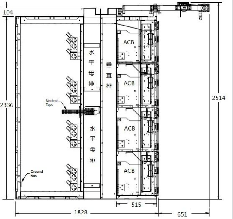
Draw-out frame circuit breakers are used in IEEE C37.20.1/UL1558 low-voltage armored switchgear, while fixed frame circuit breakers are used in UL891 distribution panels. Cables are connected via mechanical lugs (MECHANICAL) or compression lugs (COMPRESSION).
Mechanical lugs require inserting the cable and tightening with bolts; compression terminals are commonly used in China, where a tool is used to crimp the cable into the terminal nose.
For 1200A: Use 4 x 500 MCM copper cables with a minimum bending space of 330 mm, or 3 x 750 MCM copper cables with a minimum bending space of 483 mm.
For 1600A: Use 5 x 500 MCM copper cables with a minimum bending space of 330 mm, or 4 x 750 MCM copper cables with a minimum bending space of 534 mm.
For 2000A: Use 6 x 500 MCM copper cables with a minimum bending space of 330 mm, or 5 x 750 MCM copper cables with a minimum bending space of 534 mm.
For 3000A: Use 8 x 500 MCM copper cables with a minimum bending space of 330 mm, or 7 x 750 MCM copper cables with a minimum bending space of 534 mm.
For 4000A: Use 11 x 500 MCM copper cables with a minimum bending space of 330 mm, or 9 x 750 MCM copper cables with a minimum bending space of 534 mm.
For 5000A: Use 14 x 500 MCM copper cables with a minimum bending space of 330 mm, or 11 x 750 MCM copper cables with a minimum bending space of at least 534 mm.
Molded Case Circuit Breaker Output Connections
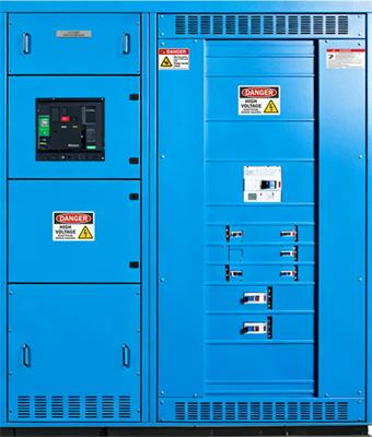
Fixed molded case circuit breakers are used in UL891 distribution panels or UL67 enclosures. Molded case circuit breakers typically come with built-in mechanical lugs. When ordering, specify the lug type, as standard configurations vary by manufacturer. Reference specifications for standard lugs are as follows:
 For 150A: Maximum 2/0 cable, cross-sectional area 67.4 mm², minimum bending radius 152 mm; minimum bending space for 3 cables is 190 mm.
For 250A: Maximum 300 MCM cable, cross-sectional area 152 mm², minimum bending radius 254 mm.
For 400A: Maximum 400 MCM cable, cross-sectional area 203 mm², minimum bending radius 330 mm.
For 600A: Maximum 2 x 350 MCM cables, cross-sectional area 177 mm² each, minimum bending radius 305 mm.
For 800A: Maximum 3 x 300 MCM cables, cross-sectional area 152 mm² each, minimum bending radius 280 mm.
For 1200A: Maximum 4 x 350 MCM cables, cross-sectional area 177 mm² each, minimum bending radius 356 mm.
This document is compiled based on UL891 standards for reference only. Actual implementation must comply with applicable standard requirements.
The cross-sectional area of an American standard 2/0 cable is approximately 67.4 mm².
The cross-sectional area of an American standard 300 MCM cable is approximately 152 mm².
The cross-sectional area of an American standard 350 MCM cable is approximately 177 mm².
The cross-sectional area of an American standard 400 MCM cable is approximately 203 mm².
The cross-sectional area of an American standard 500 MCM cable is approximately 253 mm².
The cross-sectional area of an American standard 750 MCM cable is approximately 380 mm².
Draw-out frame circuit breakers are used in IEEE C37.20.1/UL1558 low-voltage armored switchgear, while fixed frame circuit breakers are used in UL891 distribution panels. Cables are connected via mechanical lugs (MECHANICAL) or compression lugs (COMPRESSION).
Mechanical lugs require inserting the cable and tightening with bolts; compression terminals are commonly used in China, where a tool is used to crimp the cable into the terminal nose.
For 1200A: Use 4 x 500 MCM copper cables with a minimum bending space of 330 mm, or 3 x 750 MCM copper cables with a minimum bending space of 483 mm.
For 1600A: Use 5 x 500 MCM copper cables with a minimum bending space of 330 mm, or 4 x 750 MCM copper cables with a minimum bending space of 534 mm.
For 2000A: Use 6 x 500 MCM copper cables with a minimum bending space of 330 mm, or 5 x 750 MCM copper cables with a minimum bending space of 534 mm.
For 3000A: Use 8 x 500 MCM copper cables with a minimum bending space of 330 mm, or 7 x 750 MCM copper cables with a minimum bending space of 534 mm.
For 4000A: Use 11 x 500 MCM copper cables with a minimum bending space of 330 mm, or 9 x 750 MCM copper cables with a minimum bending space of 534 mm.
For 5000A: Use 14 x 500 MCM copper cables with a minimum bending space of 330 mm, or 11 x 750 MCM copper cables with a minimum bending space of at least 534 mm.
Molded Case Circuit Breaker Output Connections
Fixed molded case circuit breakers are used in UL891 distribution panels or UL67 enclosures. Molded case circuit breakers typically come with built-in mechanical lugs. When ordering, specify the lug type, as standard configurations vary by manufacturer. Reference specifications for standard lugs are as follows:
For 250A: Maximum 300 MCM cable, cross-sectional area 152 mm², minimum bending radius 254 mm.
For 400A: Maximum 400 MCM cable, cross-sectional area 203 mm², minimum bending radius 330 mm.
For 600A: Maximum 2 x 350 MCM cables, cross-sectional area 177 mm² each, minimum bending radius 305 mm.
For 800A: Maximum 3 x 300 MCM cables, cross-sectional area 152 mm² each, minimum bending radius 280 mm.
For 1200A: Maximum 4 x 350 MCM cables, cross-sectional area 177 mm² each, minimum bending radius 356 mm.
This document is compiled based on UL891 standards for reference only. Actual implementation must comply with applicable standard requirements.